A Simplified Explanation of Solar Telescopes
If you have an interest in getting into Solar Astronomy you probably have a lot of questions, and while searching through the online forums for answers is a good place to start, you will have to navigate the personal opinions and the facts. It is important to have a basic understanding of how various telescopes and filters work so you can have a clear understanding of what system is right for you.
There is nothing more frustrating than buying that shiny new Solar Telescope only to be disappointing by the lack of results. And while you, like most, are probably buying on a general budget you want to get the best product for the money. And as we all know, that’s not generally the cheapest product.
It is important to align your expectations with the performance and price point of a given system. The more information you can acquire prior to your final decision will certainly increase the joy of owning and continuing to use a Solar Telescope.
Some questions that will help you decide:
- What is your budget?
- What level of experience do you have with solar telescopes?
- What size telescope is right for you?
- Where do you plan to view?
- Are you going to be using it primarily for viewing or imaging or both?
- What are the published specifications of the various systems?
- Do you plan to travel with your scope?
- What are the differences between the various manufacturers and what do those differences mean to you?
- Did the manufacturer answer your questions, if they did not…? Why?
- Safety considerations? Have they been addressed and are they published?
I will be discussing Lunt product technology in detail but will also go over some of the basic design concepts of other manufacturers for comparison. By discussing Lunt, I hope that we provide you with a full understanding of our technology and also provide you with the answers to questions about our products while also providing insight to why you should ask the same questions from the other manufacturers and get acceptable answers.
The first decision is generally a budget. “how much do I want to spend”?
The second decision is based on how you want to use your scope? Visual, Imaging, or both. While Lunt do offer systems that will allow you to view in White Light and Calcium-k line, I will assume that Hydrogen-alpha is your current interest.
Should I buy based solely on the aperture of the telescope?
The simple answer is No!
A Solar Telescope is a completely different animal to its cousin, the nighttime scope. A Solar Telescope is a multi-filter system that requires an engineered precision balance of aperture, etalon size and performance, f-ratio, etalon placement, safety filters, and out of band blocking. It is not a secret that the price of a Solar Systems increases dramatically based on the size of the etalon paired to the system. As a general rule to Lunt products, the size of the etalon increases to match the size of the aperture. We manufacture etalons from 25mm to 160mm aperture. Our 50mm aperture Solar Telescope has a 25mm clear aperture etalon.
Lunt place the internal etalon at approximately the 50% focal length of the scope. This point is an ideal trade off between etalon size and placement based on performance and eventual price.
It should be noted that the further back in the system the etalon is placed, the more issues the etalon will have with off axis light rays. The etalon may be smaller at this point and cheaper to make, but the performance will be highly degraded when compared to a bench test with a collimated source.
Etalons place toward the rear of the telescope provide for several issues. The reduction in size often requires that the etalon be placed well back in the optical path. This requires that the focal length of the optical system be extended significantly to avoid a full deterioration of the etalon performance across it’s aperture. Not only does this add cost, it generally does not allow for full disk imaging due to the extended focal length through a small aperture etalon.
There is a misconception that “the bigger the aperture the better”. Solar viewing is done during the day and can be done from just about anywhere. High humidity, thermals, smog, and low elevation all take a toll on large aperture telescopes. It is often true that under typical seeing conditions a medium sized OTA will outperform a large OTA most of the time. The large OTA will suffer more than a medium scope due to less than good skies (poor seeing conditions). This is also true for nighttime scopes.
However, the large OTA will provide far more detail and magnification during great seeing conditions. If you intend to view in an area that has great seeing conditions then you are not restricted by Aperture, therefore, a larger Aperture OTA system is probably the right choice.
Nighttime scopes are light buckets. They are being used to try and resolve faint and distant objects. The larger the aperture you can utilize given the seeing conditions, the more detail you can resolve on faint objects.
However, the Sun is not a distant or a dim object. Quite the contrary, the Sun provides far more light than we need and a Solar Telescope does not require a large aperture to resolve detail.
Large aperture systems do have some important advantages for Solar viewing. For example: a 50mm f7 system will have a much smaller image of the Sun at the image plane than a 130mm f7 system. Right off the bat the 130mm system has a higher magnification (for a given eyepiece) than the smaller system and the details can be much better resolved at even higher magnification. The smaller system will have a limitation to how much magnification you can achieve before the details are washed out and lose contrast. However, detail has nothing to do with the aperture itself. Detail comes from the precise pairing of the filter system and specifically the etalon, to the overall optical design.
Etalons:
We all talk about the bandpass of the solar telescope. A single stack system has a FWHM (Full Width Half Maximum) Bandpass of 0.7 Angstroms at 656.28nm. A DS (Double Stack) system has a general BP spec of 0.5A. But there is A LOT more to it than that.
To explain. This states that the Bandwidth is measured to be 0.7 Angstroms at the 50% peak transmission point of the etalon as measures at the wavelength of 656.28nm.
If we assume that the H-alpha line is 1A wide and any transmission of light outside that bandwidth would be bad for our system, then we can assume that this is a good spec.?
If this etalon then has an FSR (Free Spectral Range) of 12 Angstroms and we throw a 6 Angstrom trimming filter (BF) over it we can knock out all the out of band transmission of the etalon (I see some questions coming) we should have a good performing system?
Unfortunately, it’s not that easy.
What is the Peak Transmission of the etalon in the system you are looking at?
Not all etalons are created equal. We think it is safe to say that Lunt etalons have the highest Peak Transmission of all manufacturers. We have had many etalons measured independently in blind tests through a 3rd party, and highly qualified facility, and found that Lunt etalons have a PT of about 80%.
Other vendors have ranged from 60% to less than 25%. It’s generally pretty obvious who is who when looking through the scope.
If you are looking at an etalon with a PT of 80% and the BW is measures at the 50% point (40%PT), the etalon needs to be as narrow at this point as a 25% etalon is at its FWHM measured at 12.5%. Obtaining the 0.7A BP at FWHM at 80%T requires significantly more precision to the manufacture of the etalon.
But why not just make a 25%PT etalon? Because the advantage of a high PT etalon is seen in a few ways.
A lower PT etalon requires a larger aperture objective as compared to the higher PT systems right off the bat.
A higher PT system requires that the sides of its transmission curve be very steep in order to maintain the same spec at the 50%PT point. This provides for an enormous improvement in performance via resolution and contrast when double stacking.
As an FYI: Some manufacturers offer the ability to DS their systems. (I will explain how this works a little later). Some do not.
The transmission curve’s shape for an etalon is pretty much the same for all vendors. It looks like a narrow bell curve with a peak. Given that, there is an area under the curve which adds up to the total transmission of the etalon. The higher the total area under the curve (within the BW of H-alpha) the higher the detail that the system can resolve… More light of the right kind getting to the eyepiece.
Etalons get wider at the base. In general, the BW at the 2% T point is about 1A. Below the 2% we see some “leakage” in every etalon I have ever seen that contributes to “out of band” background color/glow in the view (a slight orange color to the area around the Sun). In high PT system this is more than made up for by the ability to have higher resolution at higher magnification. It is an artifact of etalon systems in general.
We will explain the science of double stacking in a later paragraph, but the fact is that a single stack etalon CANNOT perform to the specification of a Double Stack system. It is NOT the BW at the FWHM that provides the DS system its high performance, it is the elimination of the artifacts at less than 2%T while maintaining a high PT system. In essence providing a large signal to noise ratio.
Okay so we’ve talked a lot about the generalities of etalons… All specs seem to be the same.
NOTE: Some products in the marketplace do NOT even provide a specification and simply “compare” their performance to other products. We would personally avoid any product that cannot provide specific specifications to its design and performance.
So, we have reason to ask about the Peak Transmission and why it an important factor in your decision.
Here is a great post that goes into some detail regarding the placement of the etalon in the optical path and how that would affect performance. It also explains a little detail about the differences of single vs double stack.
https://www.cloudynights.com/topic/438006-not-all-filter-bandpasses-are-created-equal/
Let’s talk about uniformity.
The image that you see through the eyepiece or on the monitor when viewing is a product off all light that has passed through the etalon over its entire area.
When looking through the eyepiece the edge of the Sun did not pass through just the edge of the etalon. The center of the Sun did not pass through just the center of the etalon. The entire image is a combination of all light that passed through all parts of the etalon.
So why is this important?
Etalons are generally spec’d by either a calculation of the performance based on several factors such as %R (reflectivity) of the etalon surfaces, medium at the gap between the plates, and thickness of the gap between the plates. Lunt etalons have a theoretical specification of 0.68 Angstrom FWHM, 84% PT, 12A FSR, and 17.6 finesse. When measure on a high precision monochromator we see a PT of 80%, a FWHM of 0.7A and an FSR of 11.5A. This is probably due to small variation in the final thickness of the spacer feet we use to separate the etalon plates and small differences in the final HR of the coatings due to innate tolerances.
Etalons can be scanned across their aperture to see the changes to the CWL (Center Wave Length).
Because the solar telescope is a system that produces an image at the image plain, any change to the CWL during the scan is simply a widening of the BW of the total system. Sometimes spec’d as the RMS of the systems. ie: if the CWL at the edge is measured at 656.29nm and the CWL at the center is measured at 656.27nm, and the etalon is 0.7A wide as measure in one spot, the actual BW has increased to 0.9 Angstroms. But the more critical issue is the widening of the curve at the out of band 2%T points.
So what happens if you scan an etalon at one point and have a nice 0.7A FWHM..? only to find out that the etalon is highly un-uniform and has an actual average FWHM of 1A? Why would this happen? Well, maybe differential pressure or differential heat, ununiform spacer, ununiform coatings etc. External influences create changes to the uniformity of the etalon gap that have significant effect on the BW of the system. Lunt utilize no heat or physical compression to the etalon, we use highly precise optical monitoring techniques during our coatings and our spacer “feet” have been independently measured to better than 100 wave. More about that in a bit.
You’re still here? cool. I have a lot more to cover…
Heat:
By definition if you need to heat an etalon to get it on band, the etalon is not on band until it reaches the correct temp. It is also not at the optimal BP until it reaches equilibrium.
Heat requires power. The amount of power depends on how long you want to observe, the ambient temperature you are viewing at and how far the etalon needs to move to get on band.
The material used as the spacer layer of the etalon has a thermal expansion coefficient. Some materials expand more than others for a given change in temperature.
Given that etalons are optical systems they cannot be heated uniformly across the entire area, they must be heated from the edge.
It’s pretty obvious that if you heat an optical system from the edge it will expand the spacer layer at the edge first. It may take several minutes to many minutes for the etalon to reach equilibrium. If the system is not closed loop then the set point of the system will need to be modified based on environmental temperature conditions.
During the time that the etalon is not at equilibrium the center of the etalon is out of band and contributing to a widening of the BW. Depending on how far the etalon must move dictates the total widening of the BW.
Some of the drawbacks to heated systems (We have made many solid etalons) is the time it takes to reach equilibrium, and the inability to use the system in extreme environments. ie: very hot or very cold.
Another issue is the amount of time it takes to change the CWL. This is especially important when wanting to quickly Doppler shift high energy events such as CMEs.
A method to overcome this issue is to make the etalon small. A smaller etalon has less thermal inertia. It’s certainly true that a large etalon that requires thermal tuning would require a sophisticated heating system to prevent excessive thermal differential and thus a significant BW widening as a result.
Compression Tuning:
Compression tuning is an effective way to tune an etalon.
In an air-spaced system there are glass “feet” placed around the outside of the etalon’s high reflector surface that are used to separate the etalon plates. These feet are optically contacted to the plates to hold them together. The feet have to be precision polished to ensure that the plates are held to a fraction of a nanometer to maintain the uniformity of the gap. As discussed before any change to the gap size across the etalon will widen the BW.
So how does compression tuning work?
The glass feet have a Youngs modulus and are actually very compressible at the optical level. By physically applying pressure directly to both sides of the etalon plates you squeeze the internal feet. In fact, you can squeeze the feet enough to move the etalon through a significant CW range with a reasonable force.
Why the center foot? What are its drawbacks?.
There is a lot of information out there talking about the center foot technology and why it was invented and patented. I’m not here to discuss that.
If you look at a center foot etalon you will see several spacer feet around the edge of the etalon and one right in the center.
These feet do the job of precision spacing the etalon plates and physically pulling (or pushing) the etalon plates into parallel. Un-parallel plates lead to uniformity of the BW across the area of the etalon.
It was a way of mass-producing etalons for solar use using standardized polishing techniques. By using the center foot, the etalon plates did not need to meet the rigorous flatness requirements of conventional etalons. They could simply be “pulled” into position.
The physical compression of these systems was used early on as a way of tuning the etalon to the desired CWL. It was abandoned after a few years due to the inability to effectively compress the center foot and the outer feet uniformly. The product was the MaxScope 70.
The compression system was re-introduced for the PST. A system that did not have a center obstruction to the etalon to deal with.
If compression of the outer feet was what is needed to bring the etalon on band then the inability to be able to compress the center foot by the same method would obviously mean that the center of the etalon was not effectively tuned. The more compression needed at the edge meant a higher differential across the CA (Clear Aperture).
It should also be noted that mechanical systems are used to compress the etalon plates. Mechanical systems cannot be manufactured to optical tolerances and differential issue will occur.
It should also be noted that the feet of an etalon are used to “hold” the plates together.
These feet are broken out of a large wafer. they are generally not cut. Cutting a spacer using induces stress into the foot making the foot less likely to take a permanent bond with the glass substrates. A broken “foot” breaks along its internal fracture lines and induces no residual stress.
The compression system works because it can squeeze the feet due to their Youngs modulus.
In order to prevent differential changes to the gap size all the feet would have to be exactly the same area. The “stiffness” of the feet goes up by its area. A foot that is slightly larger than others would not compress by the same amount. Leading to a differential gap and widening of the BW.
An etalon performance is affected by off axis light rays.
Original etalons were used in laser and telecommunications devices. These systems used light that was perfectly perpendicular to the surface of the filter. It was well known that any slight tilt of the light to the axis of the filter would move the CWL.
In a solar telescope we also want to maintain a light path that is as perpendicular as possible.
Because the Sun is a large object it has an f-ratio of 109. While this is generally considered a large f-ratio it still has a small effect on etalon performance.
Two of the major drawbacks to a center obstruction is the loss of etalon surface area (working area) and the removal of the “sweet spot” of the etalon through what would have been the most perpendicular part of the filter.
The center foot also becomes and issue for high magnification viewing. Given that most large aperture systems are typically desired for their ability to do high magnification view, this would be an issue.
On smaller etalons, the center obstruction has an impact on the overall performance of the filter. However, if a center obstruction is required to maintain etalon gap requirements, it is a necessary evil.
By comparison. Trying to stuff a large aperture through a small etalon at the rear of a system increases the angle of the off-axis rays due to the need to reduce the light cone. It’s well known that rear systems require the extension of the FL. However, this generally results in only a small part of the light cone being transmitted through the etalon aperture.
Lunt places our etalons at approximately the 50% FL point and engineer the etalon size to accept the entire cone of light at that point. Ie: the larger the aperture, the larger the etalon needs to be.
While I am on the subject of the center foot…
Lunt do not use a center foot design. Our etalon plates are thicker than other manufacturers so we can polish them to high precision. In fact, our plates are so thick a center foot would not have the ability to pull “out of flat” plates parallel. Lunt have developed techniques that allow us to mass produce etalon plates to the precision required by original etalon design.
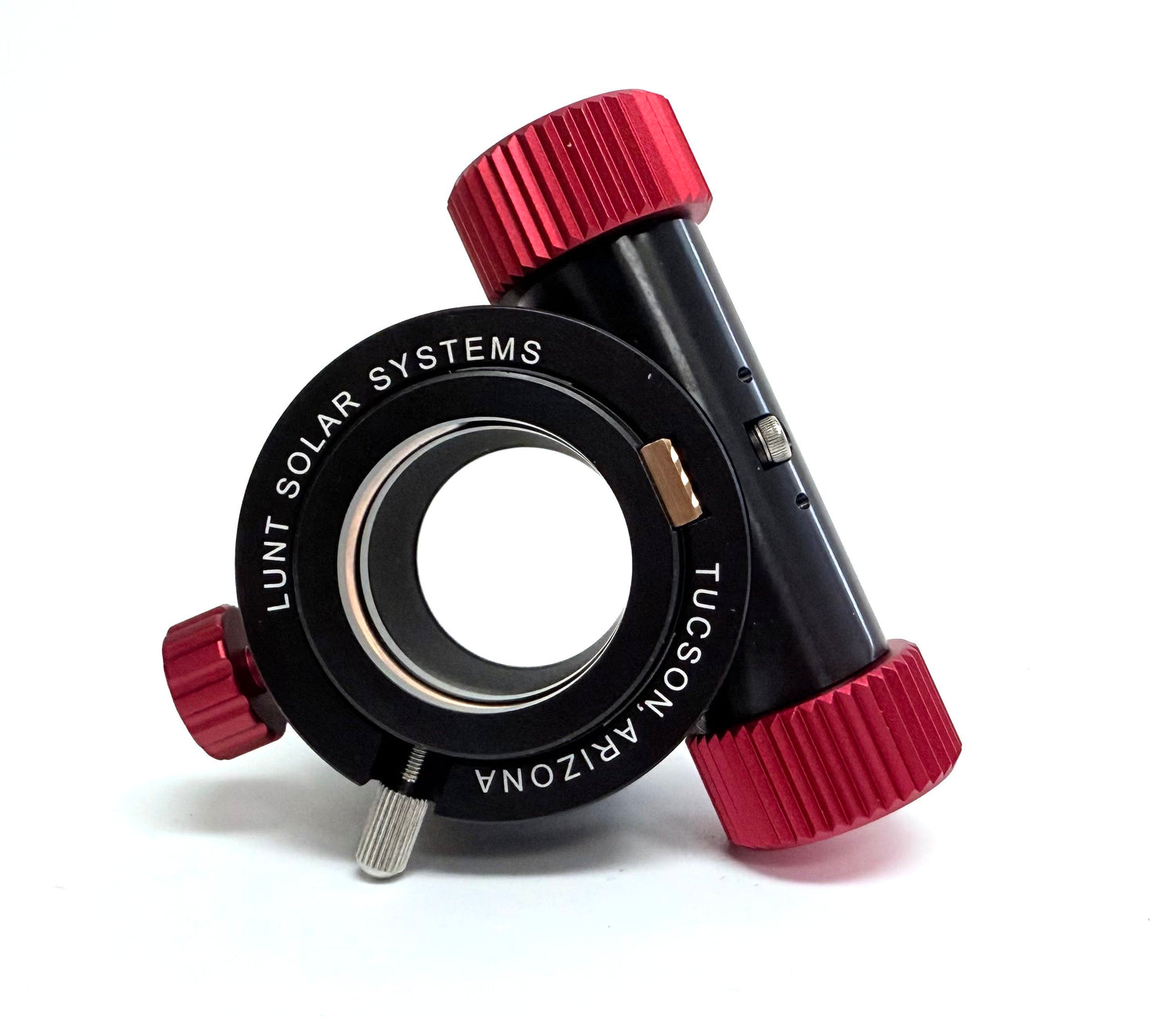
Lunt Pressure Tuning:
It should be noted that Lunt internal Pressure Tuned Etalons are matched to the Aperture and Focal Length of the Telescope. Our collimating system allows for the full aperture of the optical path through the Etalon at the optimized position. This allows us to re-focus the FULL optical path back down to the image plane, allowing for wide angle (full disk) viewing. Off course, various eyepieces can be used to zoom in on desired features. Our internal Etalons range in size from 15mm to 100mm.

The image at left shows the basic outline of this system. The internal etalon is at ambient pressure. The plunger of the pressure cylinder has just been removed and replaced. The factory tuning of the etalon is slightly low, putting the Center Wavelength (CWL) at the red wing of the Hydrogen line. This provides a view of less energetic features in the Chromosphere.

The diagram shown at left indicates that the air pressure inside the sealed chamber has been increased. At this point the CWL of the bandpass is at 656.28nm. At this position we are looking at the center of the Hydrogen-alpha line and the energy associated with that wavelength.
The sealing of the cavity is done utilizing the collimating and refocus lenses so that the etalon itself is isolated from external pressure.
The piston applies from ambient to a pressure that is equivalent to taking an etalon from -500ft to 12,000ft above sea level.
This has the added benefit of making the etalon system altitude insensitive.
In addition the etalon can be used from -0 to 150 degrees Celsius due to the fact that the tuning can compensate for the very small changes that heat would have on the “feet” of the etalon.
However, it should be noted that the Blocking Filter has a narrower useable temperature range due to it being a dielectric filter.
Lunt have recently developed a BF heating system that will allow the BF to be used in extreme cold conditions.
Pressure Tuning removes the compromises associated with internal tilt systems. Only very small adjustments to the tilt of an internal etalon can be done otherwise the etalon system will begin to suffer from the off axis rays of the re-collimated beam causing observable banding on the CCD.
People have noted that in internal tilt systems the CWL is very sensitive to even small adjustments of the tilt wheel, creating banding effects while imaging for example.
By removing the need for tilt we have placed the etalon in the most optimized position possible.
We install a very accurately tuned etalon. This etalon is tuned to the red side of the CWL. Given that it is already tuned to the red, the user has the ability to shift the tune of the CWL to the Hydrogen-alpha line and then Doppler tune to the blue or back thru to the red.

The diagram at left shows the system has been fully pressurized. This pressure is equivalent to about a very high altitude change. The air inside the sealed chamber has been compressed due to the reduced volume. As a result the refractive index of the air has increased and caused the CWL of the etalon to move to the blue or high energy side of the Hydrogen wavelength.
Due to the fact that there is no tilt involved, the image field remains flat and very precise.
Because the air pressure can be changed almost instantly with the PT knob, we can Doppler shift through to the wings H-alpha line very quickly making providing for professional level observation and study of the fast-moving events.
The Lunt Etalon is precisely mounted inside the sealed chamber using small silicone pads. These pads isolate the etalon from the body of the scope and provides for thermal isolation.
The silicone pads also isolate the etalon from vibration and help to cushion the etalon if the telescope is bumped or knocked.
The air in the cavity surrounds the entire etalon and fills the air spaced cavity. When the air in the cavity is pressurized, the etalon realizes no differential pressure change across its surfaces and the plates remain unstressed and parallel.
The air pressure can be changed inside the entire cavity instantly and without any time requirement for stabilization.
The ONLY place the change in air pressure makes a difference to the CWL is in the air space of the cavity. The increase in air pressure changes the refractive index of the air, essentially making the air thicker. This change in refractive index at the air gap changes the acceptance angle of the light passing through the etalon which results in a shift to the CWL. The increase of the refractive index exterior to the cavity has no effect on the CWL. This change in air pressure (refractive index) is both repeatable and independent to external changes in altitude and barometric pressure changes in weather.
The change in air pressure has a calculable shift to the CWL and can be used to calculate speed and energy of Solar activity. Combined with the speed at which these changes can be made, the Lunt PT provides a superior professional level instrument to the avid observer.
Competing air spaced systems are altitude and weather (barometric pressure) sensitive. Observing at 10k feet will have a completely different tuning point to these systems when compared to observing at sea level. Any change in the barometric pressure will require modification to the tuning to maintain the system on line.
The Importance of Double Stacking:
Can the product you are looking at be Double Stacked?
It is often stated that once you look through a Double Stacked Solar Telescope you don’t ever want to go back to Single Stack. While this is generally true for visual use it should be noted that the National Geographic Easter Island Live Documentary was imaged through a Lunt 60mm system in single stack mode, and the recent Great American Eclipse Live Documentary by NASA utilized 3 Lunt 100mm Solar Telescopes in Single Stack mode, all with amazing results.
A Double Stack system can also be used in Single Stack mode.
But what is Double Stack and what are benefits of having a Double Stacked system?
Double Stacking: The addition of a secondary narrowband Etalon into the telescope in order to reduce the bandpass of the system.
Bandpass: The specification of the etalon as taken at the FWHM of the measured at the peak transmission wavelength.
FWHM: Full Width Half Maximum (height) of the measured transmission curve. FWHM is measured at the 50% of the Peak transmission and represents the width of the transmission curve at that point.
This was pulled from a thread on cloudy nights. It is a statement from David Lunt.
The result of two identical etalon filters in series is a convolution of the transmission bands of each. The single etalon has a passband shape which is Gaussian. If the bandwidth at 50% of maximum transmittance is w, then that at 10% of Tmax is 3.5w and that at 1% Tmax is 10w. The transmittance at any point in the spectrum of the stacked pair is T squared, where T is the transmittance of the single filter. The most important characteristic is that the bandwidth is reduced by the square root of 2. Given two etalons with bandwidths of 0.7A, the combined bandwidth becomes 0.5A, and the 1% bandwidth (or the “tails” of the passband) are reduced from 7A wide to ~1.8A. Thus the effect is to narrow the actual bandwidth and increase the visibility of chromospheric detail, while the steeper shape of the passband reduces the out of band transmission, thus significantly improving contrast. Empahsis added.
Typically for a Lunt system, a secondary filter will reduce the bandpass from 0.7 Angstroms to <0.5 Angstroms as measured at the FWHM.
While the difference itself to the “specification” might seem small, it is what the secondary filter does to the base of the transmission curve that really matters. It is this reduction in transmission of light slightly outside the desired wavelength that really matters.
To re-iterate some previous statements for the sake of explaining the DS system:
- All Etalons are defined by the same set of specifications. All Etalons exhibit the same transmission characteristics.
- What is generally missing from the published specifications is the % of total transmission of the Etalon at the desired wavelength.
- Lunt Etalons have high transmission at the peak wavelength as designed. Generally, in excess of 80%.
- Given the 80%T (Transmission), the Width (bandpass) of our Etalons is measured at the 40% of PT point.
- Given the shape of the Etalon curve the T% widens at the base. The 2%T point is just over an Angstroms wide.
- All single Etalon systems have a small amount of T at the 2% points that obviously lay outside the FWHM bandpass.
- Even an Etalon specified at <0.4A has significant residual transmission at the base. How much residual transmission is dependent on the accuracy of the Etalon plates and its spacers.
The addition of a secondary Etalon significantly reduces this residual T, narrows the bandpass, AND cleans up the image allowing for better contrast.
The following is a very basic outline of the results of double stacking to “simplify” the understanding.
Because Etalons are interference filters, they can act together to reduce the T by the T squared at any point of the single etalon T%. Assuming both etalons have identical performance specifications.
Lunt Etalons have a peak T of 80%. A DS (Double Stacked) system will have a peak T of 80% x 80% = ~65%T. A slight dimming of the image is noted but this is more than offset by the increase in contrast.
At the FWHM, or the 40%T point: The bandpass is measured in a single system at 0.7A. In DS system the bandpass is the multiplication of the 2 interference filters, 0.7A (single) => 0.49A (dual).
By comparison a system that has a PT of 60% would have a PT of ~36% in DS mode.
For the Single Stack the 2% residual Transmission points lay outside the desired bandpass. However, in the DS system the net effect is the reduction of the 2%T points to 2% x 2% = 0.04%T. In fact, the new 2%T points now lay well within the desired bandpass and any unwanted residual light is eliminated.
To clarify a little further:
If the etalon transmission curve is understood to be Gaussian and the FWHM is 0.7 Angstroms at the 50% PT point, then the BP will be 7 Angstroms (10x BP at FWHM) at the 1% T point.
By comparison, in Double Stack mode the 1% T points are reduced to ~1.8 Angstroms.
The DS transmission curve has become notably narrower at the FWHM, but more importantly, it has become significantly narrower at the base. This has a much larger impact on the contrast and details than what may be implied by the 0.7A to 0.5A specification.
The h-alpha emission line can now be contrasted to a higher level. A Single Stack system is narrow enough to resolve the features contained on this line and will display Prominences, Spicules, Filaments, Fibrils, and Flares. Edge details are particularly well resolved at 0.7A due to the higher transmission (when compared to DS) and has the ability to contrast against the dark background at the emission line.
I like to think of this as “looking at the details”.
The DS system provides a narrower slice of the details. The narrowing of the bandpass increased the contrast and “pops” the details. With the added ability to Doppler shift (explained in Tuning) from one wing of the h-alpha line to the other (red to blue) you can dissect the fine details.
I like to think of this as “looking into the details”. The larger the scope, the more “into” the details you can get via higher magnification assuming good seeing conditions.
Back when Lunt first began the only way to DS a system was to add an “expensive” Etalon filter to the front of the Telescope (Large Etalons are difficult to make and priced accordingly). In some cases, the front filter was as much as the entire dedicated Solar Scope. However, the results were very impressive and definitely worth the extra cost.
Technology now allows for the DS to be placed internally to the Solar Telescope. By placing the DS system in a smaller part of the optical path we can use a smaller Etalon. This reduction in the size of the Etalon significantly decreases the cost of the secondary DS system even when you take into account the added pressure tuning, mechanics and optics.
The addition of the internal Etalon has all the advantages of the front mounted version as far as narrowing of the bandpass is concerned.
The slight drawback to an internal DS system is the “glow” that the back reflections of the 2 Etalons have. Generally speaking this glow can be seen when viewing full disk images. However, it is generally not noticeable at higher magnifications especially when observing the surface details. This glow can be reduced via the use of an additional filter in the system (optional accessory) should full disk imaging be an issue.
It is generally agreed that the increase in resolution and significant increase in fine detail more than make up for the slight glow at low magnification.
It should be noted that the DS system is easily removed and re-installed into the Solar Telescope as needed.
When choosing a Solar Telescope system, I often advise people to get a Double Stack. If the choice came down to a 100mm Single Stack system vs a 80mm Double Stack system I would advise the 80mm DS. They cost about the same, but keep in mind that the cost of adding the DS to the 100mm later is somewhat significant.
However, I would take a DS 100mm over a DS 80mm any day…
Thermal Stability:
Lunt etalons are thermally stable having a shift of approx.. 1 Angstrom per 212F.
The limiting factor is generally the blocking filter. The 3rd party military spec’d trimming filter used in the blocking filter has a useable temperature range of approx.. 30F – 120F. The CWL of the trimming filter will shift through the range of temperature change, but maintains its performance because it is 6 Angstrom FWHM. Lunt have developed an optional heating system so the BF can be used in extreme cold conditions for many hours.
Safety Standard:
At Lunt Solar safety is our top priority. When Lunt Solar started making solar telescopes and filters, the subject of eye safety was at the forefront of design. Our designs were approved by a senior ophthalmologist professor at a leading University of Ophthalmology in Canada. A safety criterion was determined for both UV and IR transmission. This criterion basically set the bar at less than 1×10⁻⁵ (T) for any hazardous radiation.
Several standalone filters in Lunt products meet this criterion as a single unit. However, Lunt sets double and sometime triple standards for this requirement so that in the unlikely event one filter fails, the user will still be fully protected.
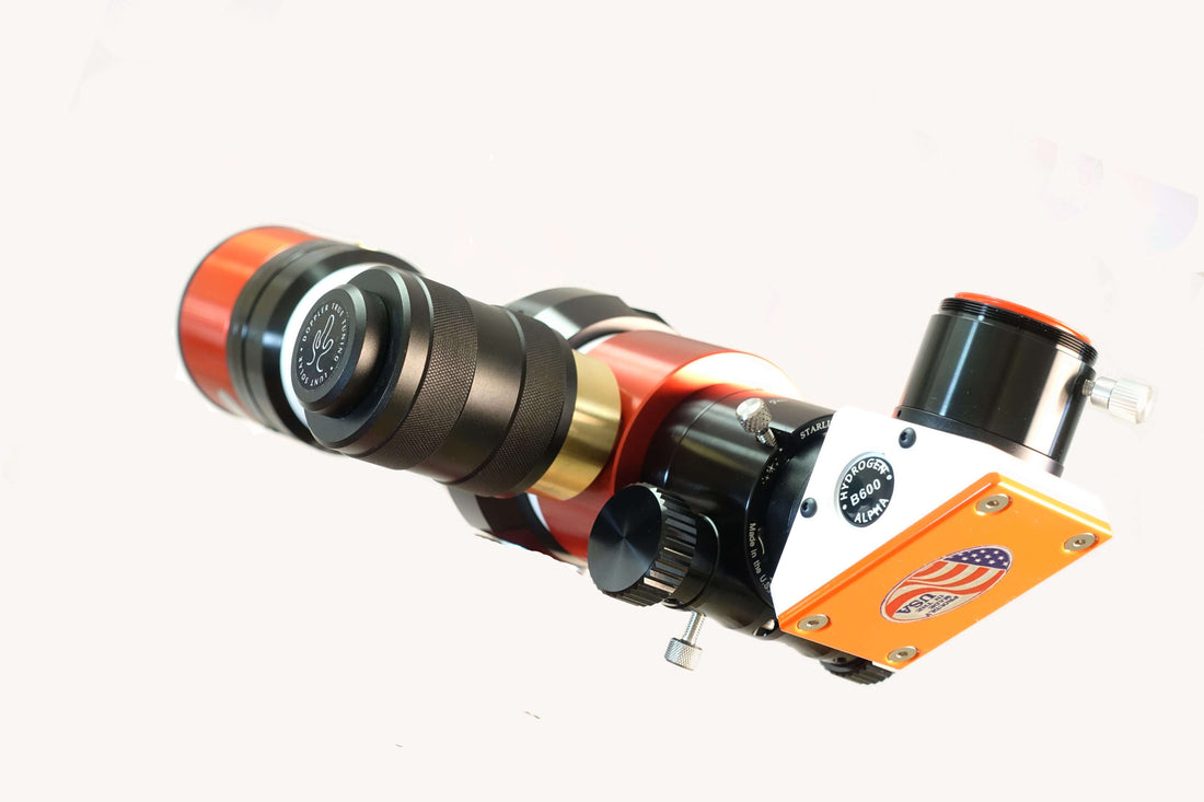
Our Filters
Energy Rejection Filter – The filtering of a Lunt system starts with a “true” energy rejection filter at the front of the system. This filter is unique to Lunt, and blocks both dangerous UV and IR. On smaller telescopes the ER filter is seen as a red-looking filter installed at a slight angle (to remove internal ghosting). This is either installed at the front of the scope or just inside the main objective. On larger aperture telescopes, Lunt puts an additional IR blocking filter onto the front surface of the main objective. This will remove all heat load from the internal parts. Even on these large aperture systems we still provide the secondary red ERF just inside the objective.
Etalon – The next “filter” in the system is the heart of the system, the etalon. While the etalon was not designed as a safety filter. However, it does have a very high reflective surface that rejects most UV (T). Significant, this would reject the majority of all IR if no prior IR filters were present.
BG Filter – The third filter is the Schott-designed BG (Blue Glass) filter. This filter is also created to absorb any residual IR.
Long Wave Pass Filter – The next filter is commonly called the diagonal “mirror”; however, it is not a mirror at all. Inside the diagonal is a Long Wave Pass filter. To begin with, it is designed to reflect a specific percentage of the 656nm wavelength to attenuate the image to a manageable brightness. It sits at a 45 degrees angle and passes thru any IR into the backing plate.
Blocking Filter – The next filter is the blocking filter. Again, this is not a safety filter unto itself. As the name implies, it blocks out-of-band wavelengths. Furthermore, this allows the h-alpha to pass and blocks all out of band transmission.
Red Glass Filter – The final filter is another piece of the red glass (without the IR coating). This glass blocks 100% of all UV. It also acts to stop the back reflection of your eyeball from the very bright BF.
Redundant Filters:
People ask why we incorporate so many IR and UV filters in the system. The multitude of safety features we employ insures that our customers will be protected. They are protected even if they use our products improperly. For instance, should a person accidentally place a standard night time diagonal in the rear of a solar telescope, the view would be bright, but safe.
Because of the addition of multiple filters and safety features, a person simply standing in the sunlight will receive more ambient UV and IR radiation to the eye than when they are looking through one of our solar telescopes.
Lens Coating:
Lunt purchases our raw etalon glass materials from a ISO qualified company on the east coast of the United States. We grind, edge, bevel, and polish all the glass needed for the etalon and filter systems in-house in Tucson, AZ. Some coatings are outsourced to a facility that maintains a coating specific to our requirements. Our coating facility has the required ability to produce AR coating at less than 0.1%R (typically in the 0.06%R range). They also hold the high reflector coatings to better than +/-1%. The ability to control the coating processes to such high accuracy has allowed us to make precision modifications to the coating formulas, which have proven to increase contrast through the reduction of background noise.
Quality Assurance:
Each coating batch is provided with full scans of the coating applied and is certified to meet any and all safety requirements. Some of our precision-coated filters are provided to us from a US military-qualified company who provides full Mil certifications with every filter.
All Lunt Solar products are 100% safe when used as directed and are shipped from the factory free of any damage or defects. If a Lunt instrument is ever dropped or damaged, it should be returned to the factory for testing and re-certification.
Due to different optical arrangements in design, a Lunt solar product should never be mixed and matched with components made by other companies.
One of the most important questions to ask when looking at a Solar Telescope is whether or not is has taken your safety into the highest consideration.
Does the system have redundant safety features to protect you if something should fail?
Does the system come with a Blocking Filter that contains additional safety features?
Have the safety feature of the system been explained and detailed or are they simply implied?