
How a Lunt Etalon is Made (Part 2): Coating, Assembly, and Testing
If you missed Part 1, that is where to start. We covered the raw material selection, beveling, grinding, and the polishing process that gets the fused silica plates to the surface quality we need. This article picks up where that one left off. Read Part 1: How a Lunt Etalon is Made →
It has taken me longer than I would like to admit to finish this. Part 1 went up in 2019 and the follow-up has been sitting on the to-do list ever since. Better late than never.
Step 2: Optical Coating
Once the plates come out of the polishing room and pass inspection, they go out for coating. This is the one step in our etalon process that we do not do ourselves, and that was a deliberate decision we made years ago.
Optical coating has become a highly specialized field. The equipment required to deposit consistent, repeatable multi-layer dielectric coatings is expensive, and the metrology needed to verify those coatings properly is just as expensive. There are facilities that do nothing else, and they are very good at it. We made the call early on that partnering with one of those facilities was going to produce better coatings than we could achieve running our own chamber. That has proven to be the right call.
What comes back from the coating facility are plates with precisely controlled reflectivity at 656.28 nanometers. The reflectivity of those coatings is the single biggest determinant of the etalon's bandpass. Get this right and everything downstream goes smoothly. Get it wrong and no amount of work in the assembly process fixes it.
Every batch of coated plates is measured when it comes back before any further work begins. If the coatings are not within specification they go back. This does not happen often, but it happens, and catching it here saves a lot of time compared to finding the problem after the etalon is assembled.

Step 3: Spacer Setup
This is where things get interesting, and where I am going to be deliberately vague. Spacer setup is the process of establishing the precise cavity gap between the two plates. The gap determines the resonant wavelength of the finished etalon, and the uniformity of that gap across the full aperture determines the uniformity of the spectral performance.
There are established ways to do this and then there are the approaches you develop yourself over years of building these things and figuring out what actually works. What I will say is that the target gap for our etalons is on the order of 0.007 inches, which is roughly 178 microns. Holding that gap to the tolerances that matter for the finished spectral performance, across the full aperture of the larger etalons, is not a trivial problem. The solution we use has been refined over a long time.
I am not trying to be mysterious about this. It is just that some of what we have developed here is the accumulated knowledge of many years of production experience, and it is the part of the process I am least inclined to describe in detail on a public website.
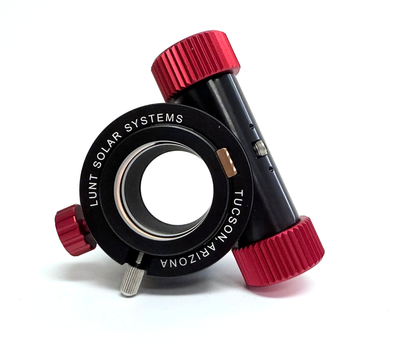
The image shown is of a solid etalon manufactured onto a spacer. The fused silica wafer is 75mm diameter x 0.007" thick. The transmitted wavefront was measured at BNL to better than 1/100th wave across the entire aperture. Both sides are coated with a dielectric hard coating to match the required etalon specifications. These wafers are also manufactured without coatings and cut up to make the "feet" or spacer layer of our Solar Etalons.

Step 4: Contacting
Contacting is the process of bringing the two coated plates together to form the etalon cavity with the spacers in place. The plates are placed in contact under carefully controlled conditions. When done correctly, optical contact forms naturally between the glass surfaces at the edges where they touch, and the spacers hold the center at the designed gap.
The reason this step matters is that the plates have to come together without trapping dust, without introducing stress that deforms the optical surfaces, and without disturbing the spacer geometry that was set up in the previous step. A contaminated contact is a wasted etalon. You cannot open it back up and try again without starting over.
Clean room conditions are not optional here. The plates are cleaned immediately before contacting and the process happens in the cleanest area of the facility. Even a single dust particle landing on a plate at the wrong moment is a problem.

Step 5: Testing with the Hydrogen Spectral Lamp
Once an etalon is assembled it gets tested using a hydrogen spectral lamp. The lamp produces a clean emission at 656.28 nanometers, which is exactly the wavelength the etalon is designed to pass. When you view the lamp through the assembled etalon you see a ring pattern. The characteristics of those rings tell you a great deal about the etalon’s performance: the center wavelength, the uniformity across the aperture, and whether the cavity gap is where it should be.
Reading those rings accurately is a skill. Our assembly personnel are experienced at it and can match the ring pattern to the target CWL quickly. It is the kind of thing that looks deceptively simple once someone knows what they are looking at, and takes real time to develop. It is also fast, which matters when you are working through a production run.
The 1.5 meter monochromator comes into the process differently. We use it to test random samples from production runs, to verify custom etalon systems, and occasionally when a finished instrument is not performing on the Sun the way we expect. That last situation is rare, but when it happens the monochromator gives us the quantitative data we need to understand why.

Step 6: Assembly in the Telescope
Once an etalon passes testing, it moves to the assembly area where it gets installed in the telescope or filter housing. The etalon has to be mounted in a way that holds it securely without introducing stress. Stress on the optical surfaces changes the surface figure and degrades the performance we just finished measuring and verifying.
For our pressure-tuned systems, the etalon assembly goes into the sealed pressure chamber at this stage. The chamber has to be clean internally, and the sealing has to be done properly. Once it is sealed it is not being opened again under normal circumstances.
The pressure tuning system connects at this point. The tuning knob, the pneumatic pathway, and the seals that maintain the chamber pressure all get assembled and verified. If you are curious about how the pressure tuning actually works and why we do it that way, I wrote about that in a separate article: How a Solar Etalon Works.

Step 7: Testing on the Sun
This is the step I always look forward to. The finished instrument goes outside and gets pointed at the sun. Everything we did in the shop either shows up properly on the solar disc or it does not.
We are looking at the full picture here. Prominences on the limb, surface detail, contrast, uniformity across the field. The spectral lamp test confirms the CWL is right. The sun tells us whether the whole instrument performs as a system. Occasionally something that looked fine on the bench reveals an issue in actual use, and it goes back for attention. More often the sun confirms what the lamp test predicted.
There is also something to be said for the fact that this is the actual environment these instruments were designed for. Testing under real observing conditions, with a real solar image, is the final verification. No bench test fully replicates that.

That is the complete process from raw glass to finished instrument. If you want to go back to the beginning, Part 1 covers substrate selection, beveling, grinding, and polishing: How a Lunt Etalon is Made, Part 1 →